If you are an electronic lover or you modify cars, you may feel the problem with inadequate power with your Starter (Main) Battery. Because the battery is decided and fixed only for the default power requirements and when you apply additional Audio Systems, Lights, Cameras Security Systems and applications like refrigerators, you have to use extra power.
You must be more careful to add more electronic devices to your vehicle as the manufacture has already calculated the required current for the existing components of the vehicle and the based on the power requirements, they have used the battery. When you add more devices, the power may not enough to operate the essential components of the vehicle.
Then how you apply an additional battery for your electronic components?
If you connect directly the 2ndbattery to the Starter battery, the problem is, when 2nd battery dry out 2nd battery will be charged by Starter Battery. Even the engine power off that will happen. Bad effect is, your car will not start.
When applying a 2nd Battery following condition should be satisfied.
- Both batteries should be charged when car engine is on.
- Both batteries should be disconnected when the engine is off
To satisfy the above, we apply a unit call “Battery isolator”. There are two types of solenoids
01. Diode isolators are commonly used. This unit is with two high current diodes. But the biggest disadvantage is, voltage drop due to the diodes and you have to change the Alternator Wiring.
02. Relay isolator or Voltage Sensitive Relay (VSR) is operated with a relay, when the engine is started the voltage goes higher than the normal voltage, then the voltage level is detected by the circuit and switch on the relay. This system is the most efficient system than diodes.
Initially you have to find one of above isolators and if you purchase one it will be around USD 23 or more. Therefore, if you follow the following lesion, you can make one Voltage Sensitive Relay unit less than USD 5.
This unit is better for a device that the battery level is more than 13.9v when the engine is on.
1 K (2W) Resistor – 01
10k (1/4W) Resistor – 01
12v (1W) Zenner Diode – 01
1N4001 Diode - 02
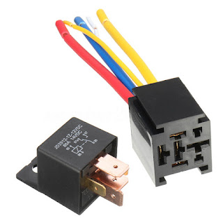
12v (80A) Automotive Relay – 01
TIP 31C Transistors – 01
Circuit Diagram is as follows.
PCB design is as follows.

Main Battery pin should be connected to the + pole of the Starter (Main) Battery
2nd Battery pin should be connected to the + pole of the 2nd Battery
GND pin should be properly grounded.
If you connect the battery wires with VSR correctly, you can start the vehicle. Then you can see the indicator LED light up and start to charge the both batteries. Once the engine is off, VSR unit will stop the operation and the connection with both batteries will be disconnected.
If you have any problem with VSR, put in the comments and the entire wiring system will be discussed in next lesson.


0 comments: